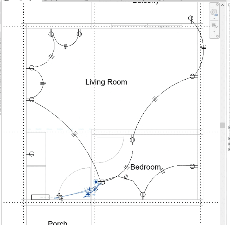
drafting

Revit MEP Basics - Adding Electricals

As architects and designers navigate the ever-evolving landscape of building projects, the integration of electrical systems becomes a pivotal element in ensuring functionality, sustainability, and future-proofing structures. In this blog, we walk you through the process of incorporating electrical systems into your architectural drafting project.

Choosing a template file

This step is optional. If you don’t have a specific floor plan in mind yet, consider choosing an Architecture template file and create your base file here. 

This stage is important as it forms the base file for your electrical template. For more details on the creation of an Architectural Template File, you can check our previous blog. 

Electrical Template and Linking Revit File

After configuring your settings, proceed to select an Electrical Template file for your project.

Choose “Electrical Template” from the dropdown menu, or load it via “Browse” with desired units. Load Architecture Template onto Electrical Template using “Insert” > “Link Revit.” Select your file, then “Open” for it to load in halftone on your workspace.

Space and Levels

Before proceeding, label your rooms. To create a space, begin by establishing space boundaries using the “Space Separator.” Navigate to the “Analyze” tab and choose “Space Separator.” Define your room boundaries. Once done, return to the “Analyze” tab again, select “Space,” and proceed to place your space, renaming the rooms as needed.

Panel Board

Locate your panel board in your project by going to the “Systems” tab and selecting “Electrical Equipment”/”EE” for a shortcut. Choose from pre-loaded panel boards in the “Properties” tab or browse through the “Load Family” tab. Place it on the vertical face and set the elevation height. To distinguish multiple panels, name your panel in the “General” section of the “Properties” tab. Click “Apply” when finished.

Receptacles/Outlets

Next, work on the outlets/receptacles. Go to the “Systems” tab and choose “Device”. From the dropdown, select “Electrical Fixtures”. Pick the desired receptacle/outlet for your project, ensuring you choose “Place on Vertical Face”. Begin placing them on the walls where you want the outlets/receptacles, making sure to set the correct height.

Circuits and Panel Schedule

When creating circuits, choose the desired outlets and go to the “Power” tab. Once done, select the panel to which your outlet will connect. You can individually choose outlets, or use “Edit Circuit” to highlight the ones you want on your panel.

For the Panel Schedules, choose the “Create Panel Schedule” tab and pick the template you want for your schedule. You can customize it or opt for a default template. This will automatically generate a schedule for your electrical layout.

Lighting Fixture and Switches

For the lighting plan, visit the “Systems” tab. Confirm that your fixture placement is set to “Place on Face.” Choose the lights for positioning on your ceiling. If the pre-loaded fixtures on the Properties tab aren’t suitable, you can “Load Family” for alternatives.

For switches, return to the “Systems” tab, select the “Device” tab, and from the dropdown, choose “Lighting.” Pick the switches you want to appear on your drawing plan.

Fixture connection to the panel board

Select all the lights by holding down the CTRL key and make sure that the number of volts for your lights fit the panel board. Choose one lighting fixture, then click the “Power” button. It will connect to the panel board immediately, or you can manually place them on their respective panel boards. Use “Edit Circuit” to include all the lighting fixtures for your panel.

Switch Circuit and Wiring

To connect your lights to a switch, choose one lighting fixture and then select “Edit Switch System.” Pick the “Select Switch” and choose the switch that will be connected under your lighting fixtures. Immediately after, choose “Add to System” and hold the CTRL key to select the lights under that switch. Once all is complete, click “Finish Editing System.”

Hover over one of the lights and press the TAB key; the wiring will then appear automatically. You can modify the path by choosing either an arc connection or a straight connection.

There are many ways you can document your Electrical Systems in different software. With the MEP tools in Revit, these models serve as a basis for generating detailed and coordinated construction documentation. The software’s ability to handle various parameters, from voltage requirements to load calculations, contributes to the creation of well-documented Electrical Systems that align with project specifications.

Was this insightful? Give a thumbs up or post a comment.

For more of our blogs, check out https://mgsglobalgroup.com/blog/

mgs global group linzi

Connect with us!

Trending

Podcast
with Joann Lui

Get the latest blog

466810cookie-checkRevit MEP Basics – Adding Electricals
Subscribe
Notify of
guest
0 Comments
Inline Feedbacks
View all comments