How to Model a Roof Truss on Revit
- 4 min read
- April 18, 2025
In modern building design, accurately modeling structural elements like roof trusses is essential. It ensures the building is structurally sound and that construction plans are clear and reliable. Using Building Information Modeling (BIM) tools like Autodesk Revit is key to achieving this precision.
Revit allows architects and engineers to create detailed, data-rich 3D models that reflect real-world construction. This guide provides a clear, step-by-step method for modeling steel roof trusses in Revit, balancing professional techniques with an easy-to-follow approach.
Mastering this process enhances your modeling skills and contributes to better project outcomes. Follow these six steps to create accurate and efficient truss models.
Establish Support Columns
First, define where the truss will be supported by placing columns. These columns form the structural foundation for the truss system.
Navigate to the Structure tab and select the Column tool. It’s important to choose Structural Column, as these have the necessary properties for analysis and proper connections with framing members.
Use project grids and levels for precise placement, ensuring columns are located exactly as specified in your structural layout. Before clicking to place each column, carefully review its settings in the Properties Palette.
Verify the Base Level, Top Level, and any Base/Top Offset values are correctly set. Accurate column placement is critical; errors here can cause significant problems later in the modeling process.
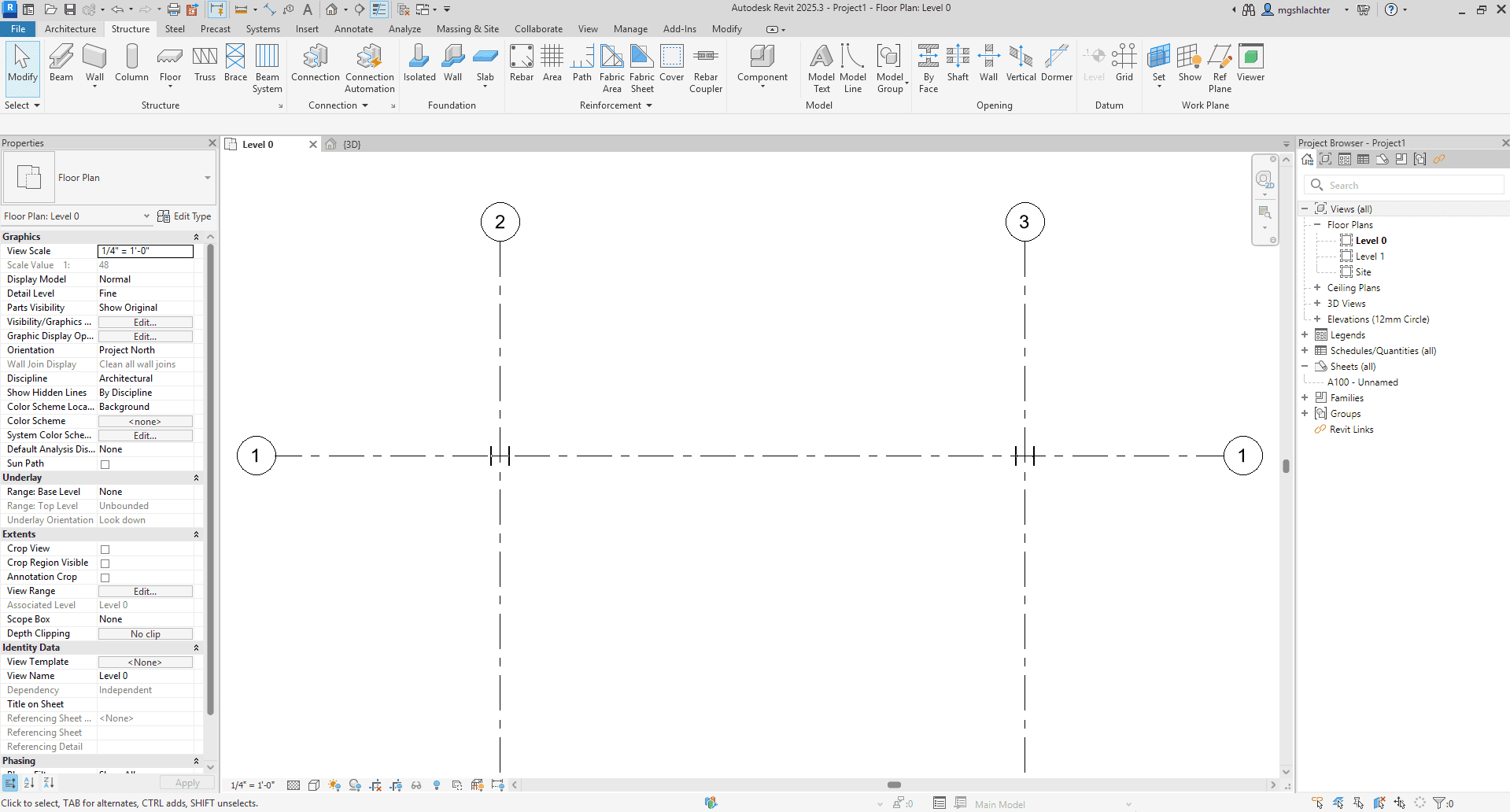
Sketch the Basic Truss Framework
With the columns in place, you can now outline the truss itself. Go back to the Structure tab and select the Truss tool.
Define the truss span by clicking on the start and end support points, typically snapping to the column centerlines or relevant points. This action creates a Truss System Family object.
Think of this object as an intelligent layout line or framework. It defines the overall geometry (span, profile) and acts as a guide for the actual structural members.
Before placing the truss line, check its Type Properties. You can select from standard truss types (like Pratt, Howe) or adjust parameters like Truss Height.
Ensure you are sketching on the correct Work Plane (the level or plane where the truss should sit). This initial sketch is the controller for the beam elements added later.
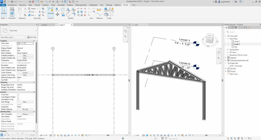
Verify the Layout in 3D View
Immediately after sketching the truss framework, switch to a 3D view for a spatial check. While 2D views are good for alignment, 3D helps catch issues with elevation or orientation.
This visual check provides crucial spatial context. Access the Default 3D View via the View tab or the Quick Access Toolbar.
Use Revit’s navigation tools (Orbit, Pan, Zoom) to inspect the truss sketch from various angles. Check its vertical position, alignment between columns, and overall orientation.
Identifying potential errors now is much more efficient than correcting them after adding beam elements. Consider this 3D verification an essential quality control step.
Load Required Structural Framing Families
The truss framework needs actual beam profiles to represent its members. You need to load these specific Structural Framing Families into your project.
These families contain the precise geometric shape (like I-beam, HSS tube) and important data for scheduling and analysis. Go to the Insert tab and use Load Autodesk Family or Load Family.
Navigate through the library to the Structural Framing category, then typically by material (e.g., Steel) and standard/shape. Select the specific profiles needed for your design.
You will likely need multiple families: distinct types for the top chord, bottom chord, and the web members (verticals/diagonals). Loading the correct profiles ensures your model accurately represents the intended structure.
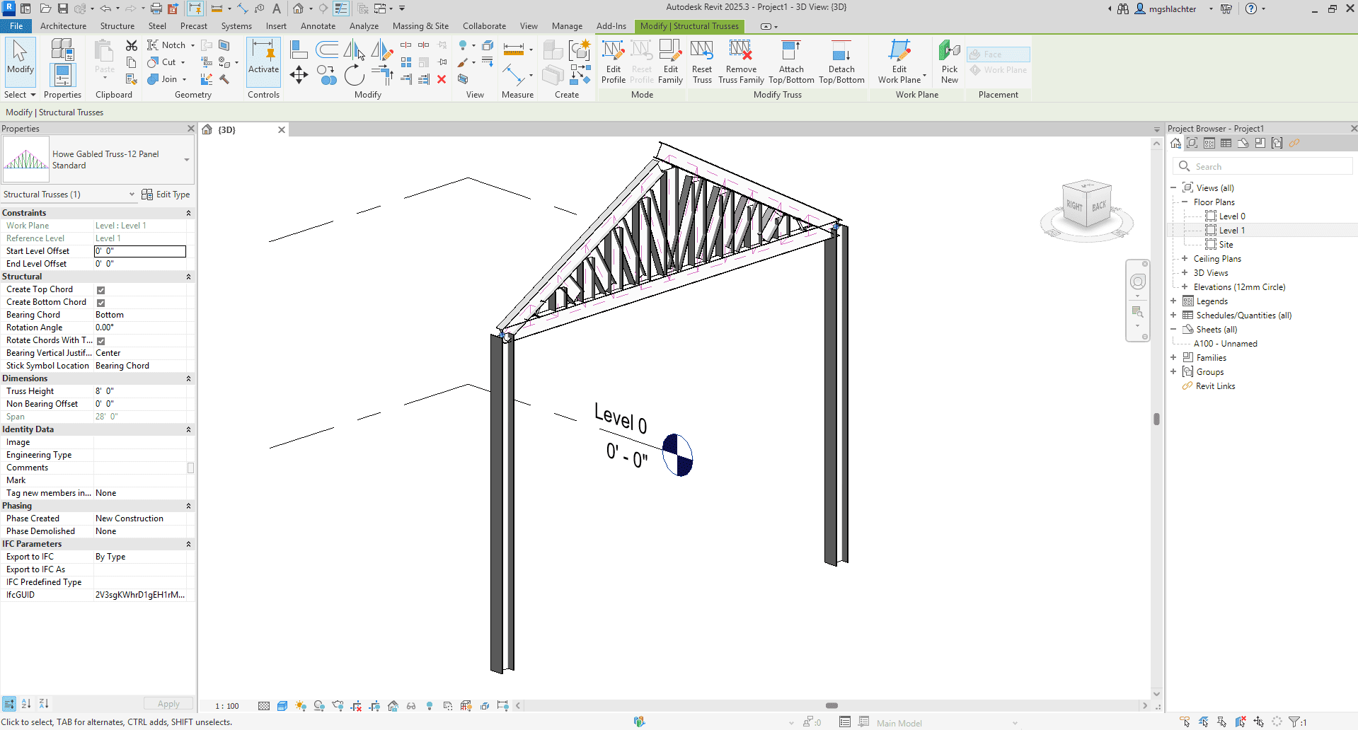
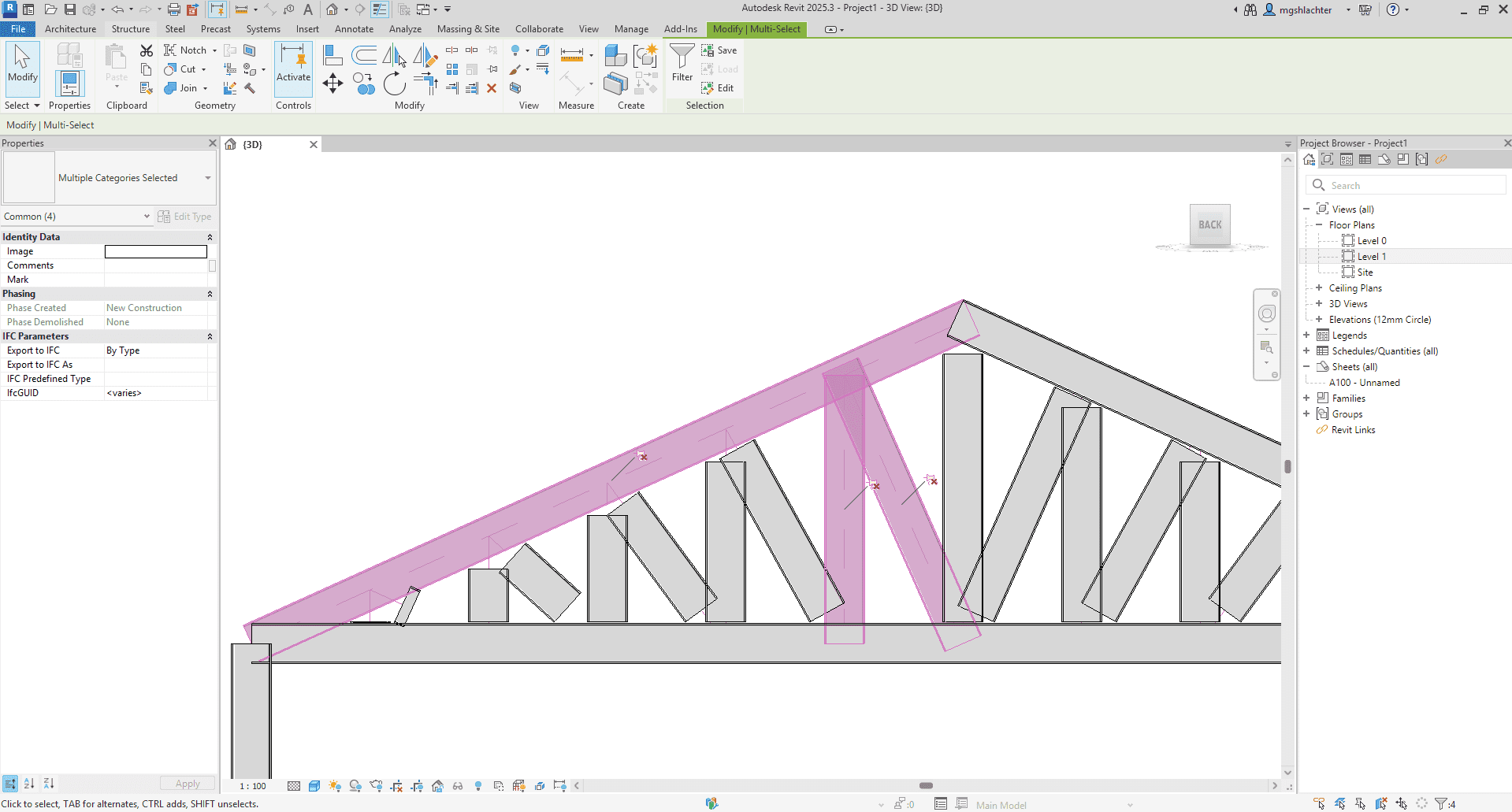
Assign Beam Families and Refine Connections
Now, apply the loaded beam profiles to your truss framework. Select the truss layout line object you created.
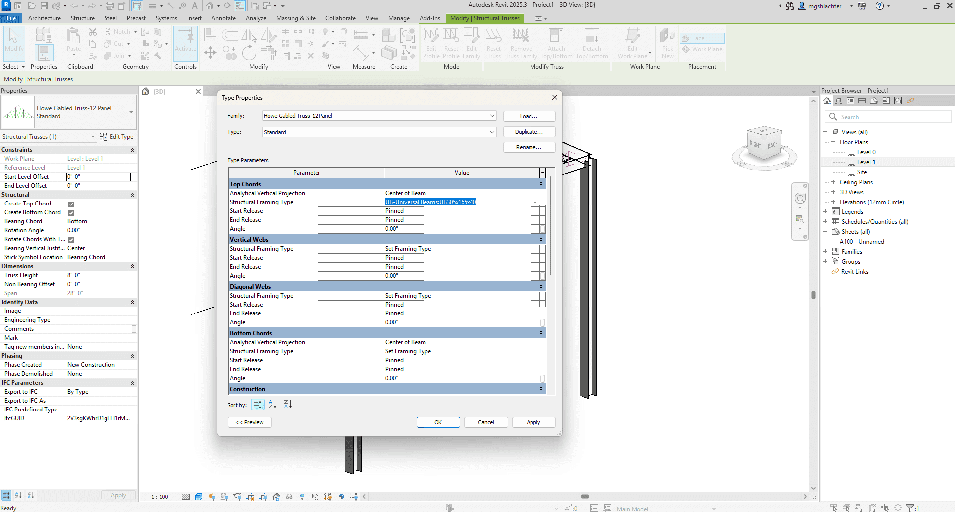
In the Properties Palette, click Edit Type. Here, you assign the specific Structural Framing Types (the families you loaded) to the Top Chord, Bottom Chord, Vertical Webs, and Diagonal Webs.
Click OK, and Revit automatically generates the beam members along the framework lines. However, the default connections where these members meet usually require refinement.
Carefully inspect these junctions in detail views or 3D. Look closely for gaps, overlaps, or misalignments between member ends.
Use tools on the Modify tab, especially Trim/Extend (TR), to clean up these intersections precisely. Achieving clean, accurate connections is vital for a correct model representation and clear construction documents.
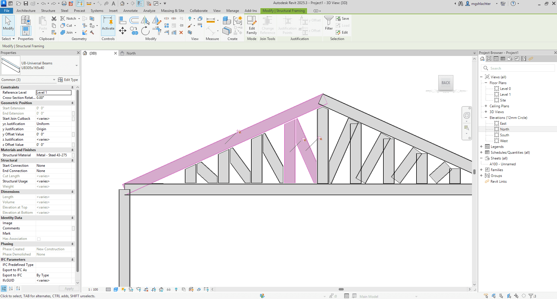
Finalize Member Positions and End Details
The last step involves fine-tuning the position and end connections of the truss members. Double-check that chords extend properly to supports and webs connect cleanly to chords.
Use the Instance Properties of individual beams to adjust their precise position. Settings like z-Justification (vertical alignment) and y-Justification (horizontal alignment), along with Offset values, provide fine control.
This ensures beams with different depths align correctly, for instance, aligning the tops or bottoms of chords. For more realistic steel detailing, consider using the Cope tool (Structure tab).
This tool cuts back the end of one member where it joins another, simulating fabrication cuts for connections. Finally, review the Analytical Model representation to ensure it aligns reasonably well with your physical model adjustments.
These final touches complete the truss geometry, ensuring visual accuracy and structural representation.
Conclusion
Following this structured, six-step process allows for the accurate and efficient modeling of steel roof trusses in Revit. This methodical approach improves the quality of your BIM model, facilitates better project coordination, and leads to more reliable construction documentation. It’s about building a digital representation you can trust.
These steps provide a solid foundation for modeling standard trusses. For a visual walkthrough demonstrating these techniques within the Revit interface, please refer to the complete tutorial on our YouTube channel.
Enjoyed this post?
Explore more resources here or book a quick call to learn how MGS Global Group can support your drafting and construction documentation needs.