How To Create Parametric Cabinets in Revit
- 5 min read
- May 8, 2025
Designing interiors often involves numerous cabinets – in kitchens, bathrooms, offices, and more. While Revit offers some basic options, creating specific designs or needing cabinets that easily resize requires building custom parametric families. A parametric family functions like a “smart” object: build it once with flexible rules, and then adjust its size and features simply by changing values.
Crafting your own parametric cabinets grants significant control over designs and saves considerable time. Instead of hunting for the perfect pre-made cabinet or manually tweaking dozens, you can develop one adaptable family suitable for various situations. This guide provides a step-by-step walkthrough for building a basic, flexible wall cabinet within Revit’s Family Editor.
The process is pretty straightforward, too. Learning this method provides more than custom cabinets; it unlocks fundamental skills for creating all sorts of smart Revit objects. Start building your first parametric cabinet by following these steps.
1. Start Smart: Choosing the Right Template and Setting Units
Every Revit family begins with a template – this provides the basic foundation for the object being built. Since cabinets typically mount on walls, a wall-based template is the appropriate starting point.
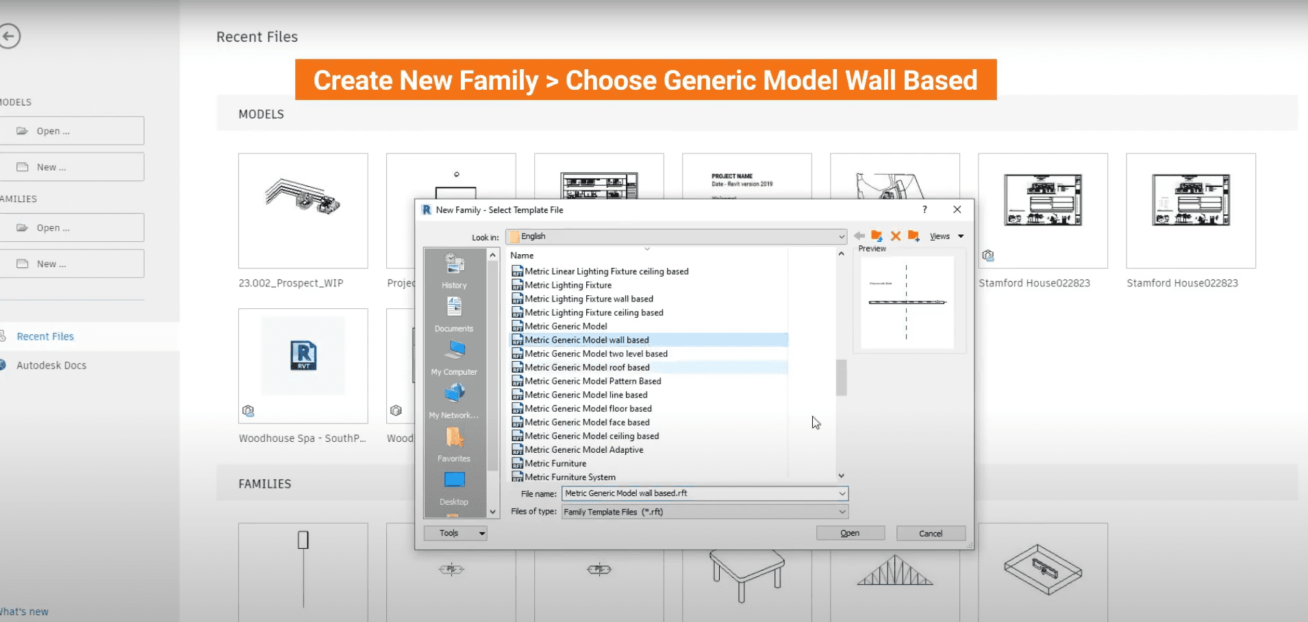
- First, go to File > New > Family.
- Revit prompts for a template file selection. Find and choose Generic Model wall based.rft. This template type ensures the cabinet appropriately attaches to wall elements within projects.
Before drawing anything, check the measurement settings. Correcting this now prevents scaling issues later.
- Go to the Manage tab and click Project Units (Keyboard shortcut: UN).
- Confirm the Length setting matches standard practice (e.g., millimeters, or feet and inches).
Click OK when done.
2. Build the Skeleton: Setting Up Reference Planes
Reference Planes are crucial; they serve as the invisible skeleton or underlying structure controlling the cabinet’s shape and size. Drawing these guides accurately is the first step in modeling.
- In the Reference Level view (a top-down perspective), go to the Create tab and click Reference Plane.
- Draw planes defining the cabinet’s outer boundaries: one for the Front, one for the Back (often aligned with the host wall), one for the Left side, and one for the Right side. Exact placement isn’t critical yet.
Now, define the vertical limits.
- Switch to the Front Elevation view (looking directly at the cabinet).
- Draw two more reference planes using Create > Reference Plane: one for the Top and one for the Bottom of the cabinet.
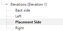
Assign names to these planes for clarity. Select a plane, and in the Properties panel (usually on the left), enter a descriptive name (e.g., “Left”, “Right”, “Cabinet Top”, “Cabinet Bottom”). Organization is key.
3. Make it Flexible: Adding Dimensions and Parameters
Turn those guide lines into adjustable dimensions using parameters. Parameters act as smart labels for dimensions, allowing easy size changes later.
- While in the Reference Level view, go to the Annotate tab and click Aligned Dimension.
- Add a dimension between the Left and Right reference planes.
- Add another dimension between the Front and Back reference planes.
Select the dimension line between Left and Right. In the ribbon menu at the top, find the Label dropdown and choose Create Parameter.
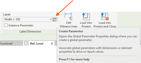
- In the pop-up box, define the smart label:
- Provide a clear Name, such as “Cabinet Width”.
- Choose Type or Instance. Type parameters apply the same value to all cabinets of this type. Instance parameters allow changing the value for each cabinet placed. For standard dimensions like width, depth, and height, Type is commonly used.
- Under “Group parameter under”, select Dimensions. Click OK.
- Repeat this for the dimension between Front and Back, naming the parameter something like “Cabinet Depth”.
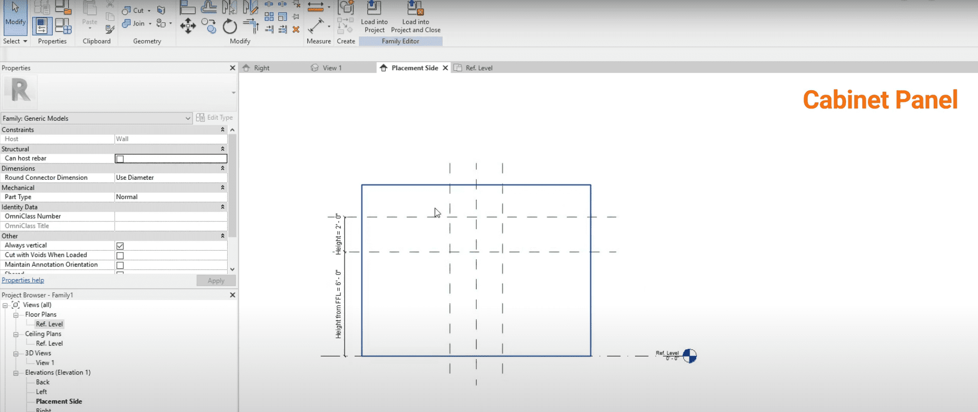
Switch back to the Front Elevation or Placement Side view.
- Add a dimension between the Top and Bottom reference planes. Create a parameter for it, perhaps named “Cabinet Height” (usually a Type parameter).
- Optionally, add a dimension from the Bottom plane to the “Ref. Level” line (representing the cabinet’s placement height) and create a parameter like “Bottom Offset” (often an Instance parameter for flexible placement).
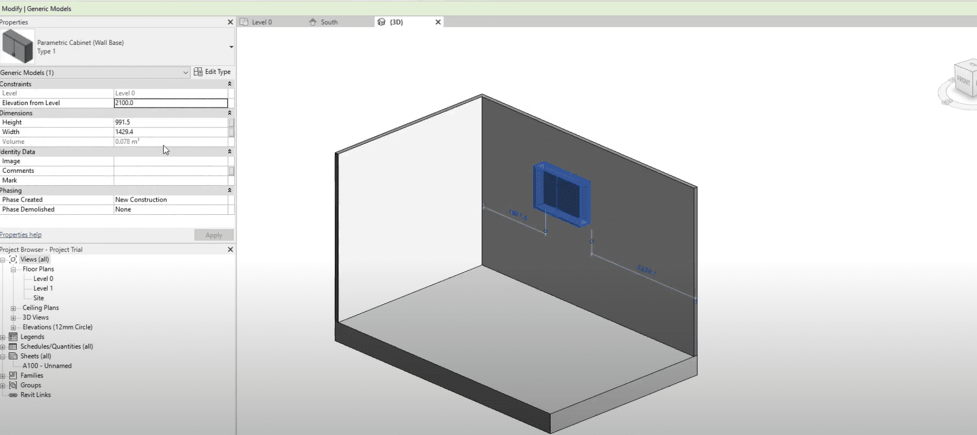
To observe the parameters:
- Go to the Create or Modify tab and click Family Types (icon resembling a small blue folder).
- This dialog box lists the defined parameters (Cabinet Width, Depth, Height, etc.). Try changing the numbers in the “Value” column and click Apply. The reference planes should adjust, confirming the skeleton is flexible.
4. Give it Form: Modeling the Cabinet Box with Extrusions
With the adjustable skeleton prepared, build the physical cabinet panels using the Extrusion tool. Extrusion involves drawing a 2D shape and “pulling” it into a 3D form.
- Return to the Reference Level view.
- Go to the Create tab and click Extrusion.
- Use the Draw tools (e.g., Rectangle) to sketch the profile of the cabinet’s bottom panel. Critically important: Ensure the sketch lines snap onto the Left, Right, Front, and Back reference planes. As each line is drawn or aligned, a small padlock icon appears. Click every padlock to lock the sketch line to its reference plane. This action instructs Revit to keep the edge attached to the guideline, enabling parametric resizing.
- Once the profile is drawn and locked, check the Properties panel. Set the Extrusion End and Extrusion Start values to define the panel’s thickness and vertical position (aligning with the “Cabinet Bottom” reference plane).
- Click the green checkmark (Finish Edit Mode) to complete the extrusion.
Repeat this extrusion process for the other panels:
- Top Panel: In Reference Level view, sketch, lock all four sides to the appropriate planes, set thickness and position vertically using the “Cabinet Top” plane, then finish.
- Left Side Panel: Go to the Left Elevation view. Create an extrusion, sketch the profile, lock edges to Top, Bottom, Front, and Back planes. Set extrusion depth (panel thickness). Finish.
- Right Side Panel: Go to the Right Elevation view and repeat, locking to Top, Bottom, Front, and Back planes.
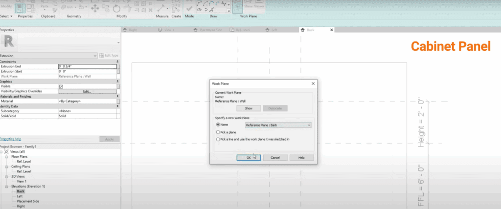
- Back Panel: Create an extrusion (Reference Level or elevation), sketch, lock to Left, Right, Top, and Bottom planes, set thickness and position near the “Back” plane.
5. Adding the Doors: More Extrusions
Creating doors follows a similar extrusion process.
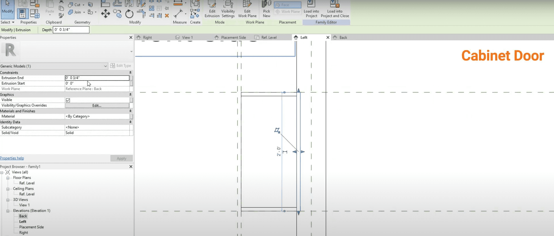
- Go to the Front Elevation view.
- Click Create > Extrusion.
- Sketch the profile of the cabinet door(s). Consider making the door slightly smaller than the opening to create a “reveal” (small gap). Extra, slightly offset reference planes can be added specifically for door edges if needed.
- Lock the door sketch lines to the relevant reference planes (either the main cabinet planes or dedicated door planes).
- In Properties, define the door’s thickness (Extrusion End/Start) and ensure correct positioning at the cabinet front.
Click the green checkmark to finish.
6. Finishing Touches: Hardware (Door Pulls)
Add realism with a handle or pull. These are often separate Revit families loaded into the main cabinet family (a technique called “nesting”).
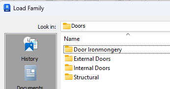
- First, load a handle family: Go to the Insert tab, click Load Family. Browse Revit’s library (look under “Specialty Equipment” or “Doors” then “Door Ironmongery”) and choose a suitable pull.
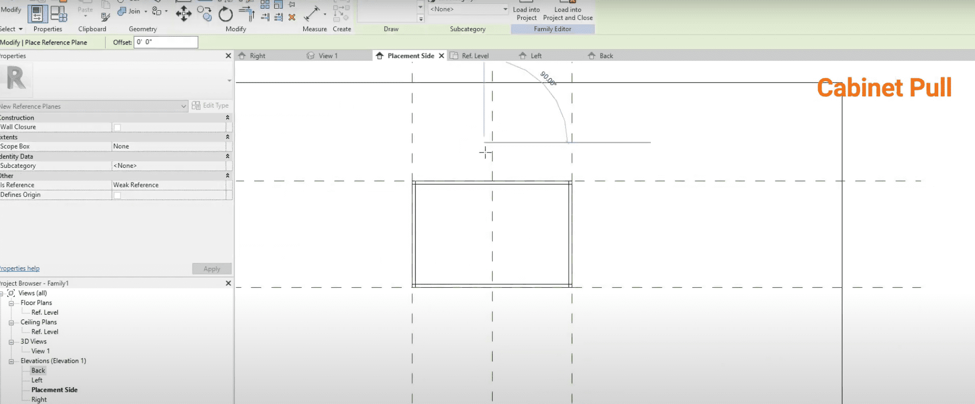
- Back in the cabinet family’s Front Elevation, draw reference planes precisely where the handle(s) should be located (e.g., one vertical plane offset from the door edge, one horizontal plane offset from the door bottom).
- Add dimensions to these new planes and create Instance parameters (e.g., “Handle Horizontal Offset”, “Handle Vertical Offset”) to allow handle position adjustments per cabinet instance.
- Go to the Create tab and click Component. Select the loaded handle family.
- Place the handle near the intersection of the new hardware reference planes.
- Use the Align tool (AL) (Modify tab). Click the vertical hardware reference plane, then the handle’s center or edge, and click the padlock to lock it. Repeat for the horizontal plane. Locking ensures the handle moves correctly with door size changes.
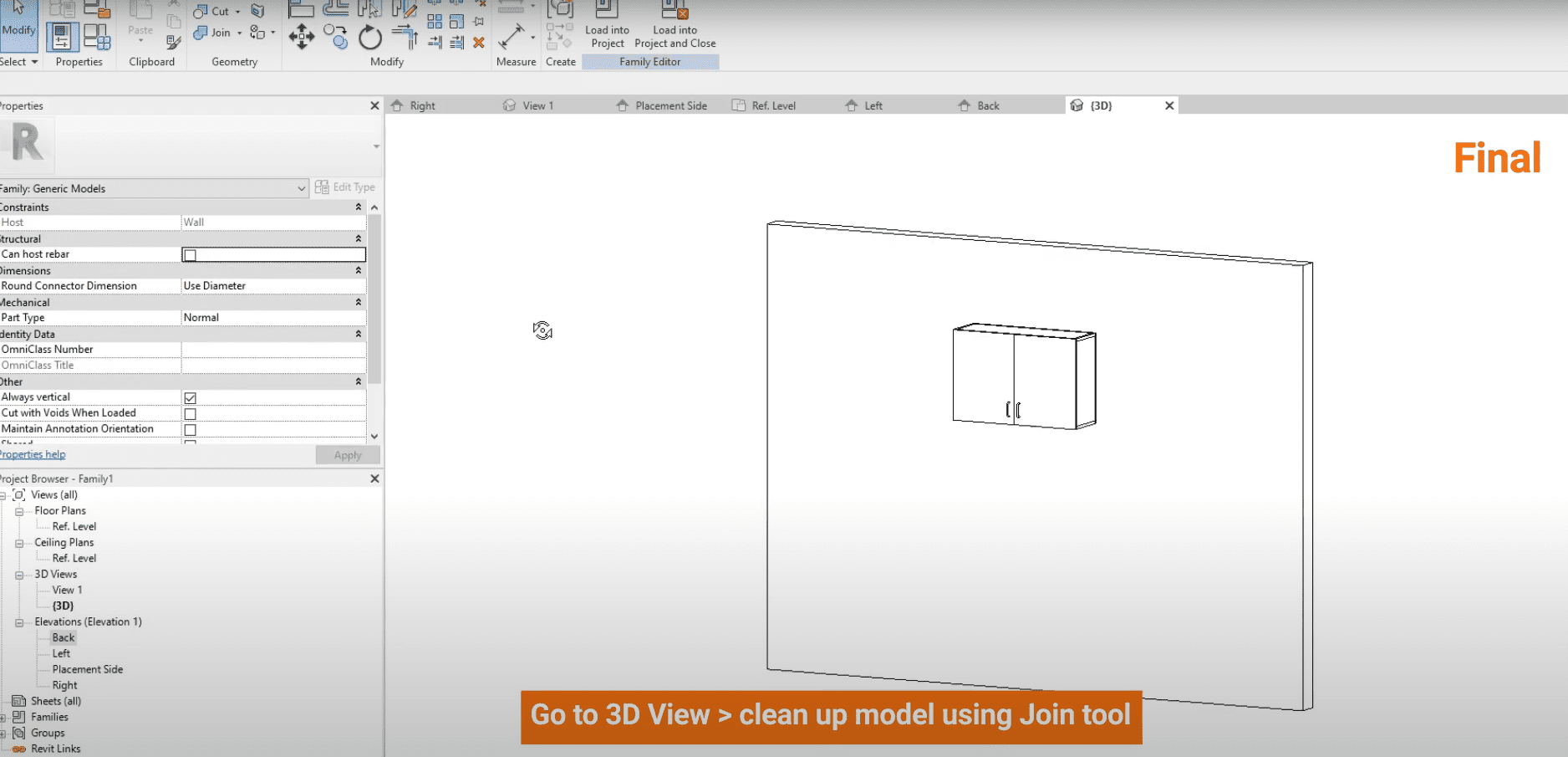
7. Clean Up and Details: Join, Materials and 2D Lines
Perform final cleanup and add details.
- Inspect the cabinet in a 3D View. If panel connections look messy or overlapping, use the Join Geometry tool (Modify tab). Click the tool, then select two intersecting panels (like the side and top) to create a clean join.
- To enable easy material changes in a project, assign a material parameter. Select a cabinet panel. In the Properties panel, find Material. Click the small associate family parameter button […] next to it.
- Click <Add Parameter…>. Create a new parameter, name it “Cabinet Finish”, group it under “Materials and Finishes”, and choose Type or Instance (Type is common). Click OK twice.
- Select the other cabinet panels and door(s) and assign this same “Cabinet Finish” parameter to them. Now, one change updates the entire cabinet’s material. A separate parameter can be created for the hardware material.
- For clear 2D drawings (like floor plans), add symbolic lines showing the door swing (these won’t appear in 3D). Go to the Front Elevation. Go to the Annotate tab, click Symbolic Line. Select a suitable line style like Hidden Lines (projection). Draw the diagonal lines representing the swing.
Common Pitfalls to Avoid
Building these smart families is great, but watch out for a couple of common slip-ups. First, always lock your sketch lines to the reference planes you created. If you forget this important step, your object won’t resize or change shape correctly when you adjust its parameters later on. Second, make testing a regular habit. Change the parameter values to “flex” the model – this helps you catch and fix mistakes early.
Another key tip: avoid making your parameters overly complicated. Keep them organized and stick to only what’s truly needed for how the family will be used. Simpler parameters make your families much easier for everyone to manage, understand, and use effectively down the road.
You’ve Built a Smart Cabinet
Congratulations! A parametric wall cabinet has been successfully created in Revit. Through the methodical setup of reference planes, the addition of parameters, and the crucial step of locking geometry, an intelligent object capable of adapting to various project requirements is now ready.
The core techniques employed here – using reference planes, parameters, extrusions, and locking constraints – are fundamental for creating many types of custom families in Revit. This initial effort in building effective parametric families yields substantial benefits through increased efficiency, improved consistency, and greater design control across projects. Continue practicing and experimenting to further develop skills in creating sophisticated custom content.
And if you want an even more in-depth exploration of these plug-in tools, you can check out our YouTube video on the subject, now live on our channel.
Enjoyed this post?
Explore more resources here or book a quick call to learn how MGS Global Group can support your drafting and construction documentation needs.